Circuit Breakers: Test plan creation using DV-Win software
With DV Power CAT Standard Series of circuit breaker analyzers & timers, you can create your test plan and use it later on a test site.
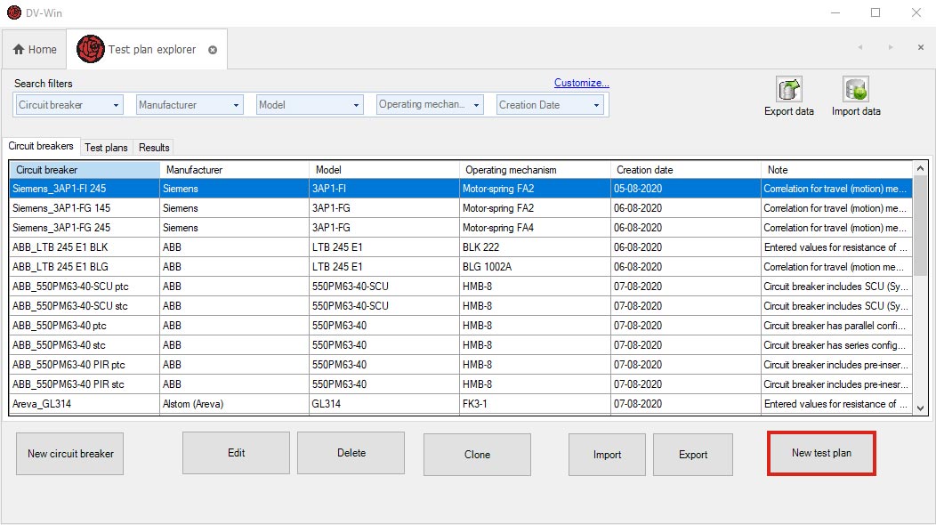
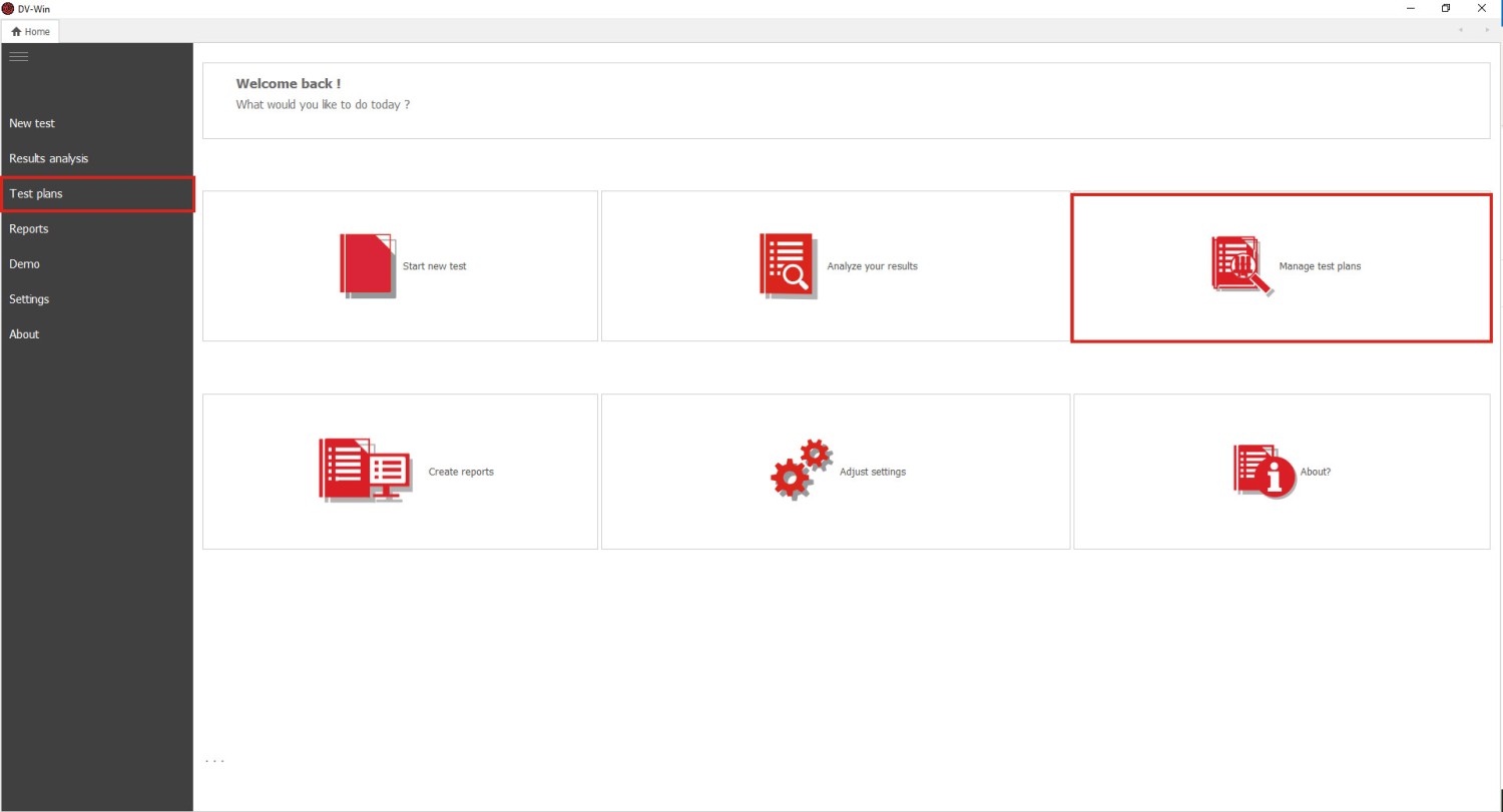
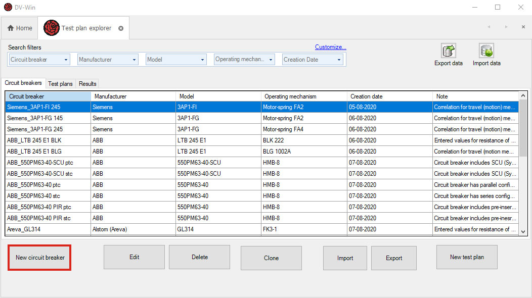
After starting the DV-Win software, a window will appear, as presented in Figure 1. By clicking the Test Plans or Manage Test Plans options (labeled in red color below) and selecting Circuit Breakers, the Test Plan Explorer window will open as shown in Figure 2. This window contains three tabs: Circuit breakers, Test plans, and Results. The Circuit breakers tab contains the list of the circuit breakers for which factory data have been entered earlier in the DV-Win system database. The Test Plans tab contains the list of all previously created test plans stored in the DV Win database. The Results tab contains the list of all test results obtained and stored so far in the DV-Win database.
Test plans are created based on circuit breakers entered in the table in tab Circuit Breakers. If the desired circuit breaker is not available in the Circuit Breakers tab, the first step is to enter the circuit breaker data for which the test plan is being created.
To enter a new circuit breaker data in the database please select the tab Circuit Breakers and then press option New Circuit Breaker (Figure 2). The window will appear for data entry, as shown in Figure 3. Mandatory fields to enter are placed in the tab CB Info, and those are Manufacturer, Model, and Operating Mechanism. Also, it is useful to enter data in other fields (Breaks per phase, Voltage level, Serial number, Breaker ID, and Notes) to provide an easier search for circuit breakers later. If data has not been entered in the field Circuit breaker name, a circuit breaker name will be automatically generated when saving data in the database.
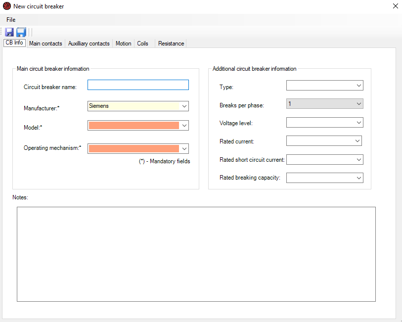
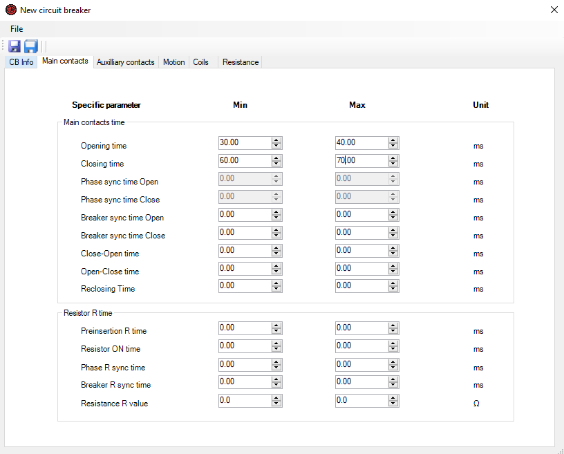
The Main contacts tab layout is presented in Figure 4. The limit values for all standard main contact timing parameters are entered in the upper part of the window. Parameters Phase sync time Open and Phase sync time Close can be entered only if the test circuit breaker has 2 or more breaks per phase. The limit values for Pre-insertion resistor timing parameters and resistance are entered at the bottom part of the window. These parameters should be filled in only if the circuit breaker has the pre-insertion resistor connected in parallel to the main contacts.
The limit values for the Opening and Closing time of auxiliary contacts are entered in the Auxiliary contact tab (Figure 5). They are filled in separately for an auxiliary contact of type “a” (which follows the main contact state) and type “b” (which has the opposite state compared to the main contact).
The motion parameters limit values such as Stroke, Contact wipe, Rebound, and Overtravel are entered in the Motion tab (Figure 6). Motion units can be selected in millimeters (mm), inches (inch), or degrees (deg). What unit will be used depends on the following:
- A unit manufacturer's limit values are expressed in (mm, inch or deg);
- A type of transducer to be used for a motion measurement (linear or rotary);
- The availability of data on correlation between a contacts motion and movable part where transducer should be mounted.
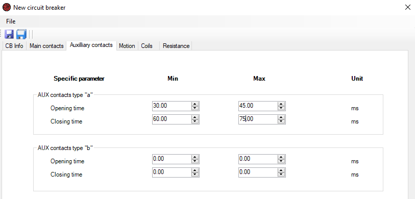
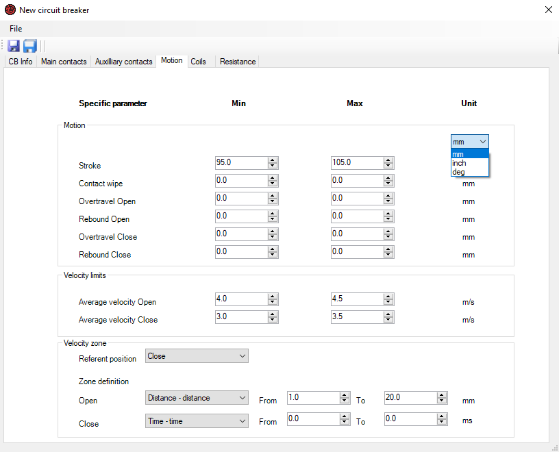
Figure 6. illustrates the fields for entering the limit values for the average velocity at opening and closing operations. The area (based on time or motion) in which the average velocity will be calculated needs to be defined in the Velocity zone field. The velocity zone is defined depending on the Referent position, which can be the Close or Open position of the circuit breaker.
In the tab Coils, the limit values are entered for the following parameters: Coil current and time, Minimum trip voltage, Maximum trip voltage, Coil resistance, Motor current, and Charging time.
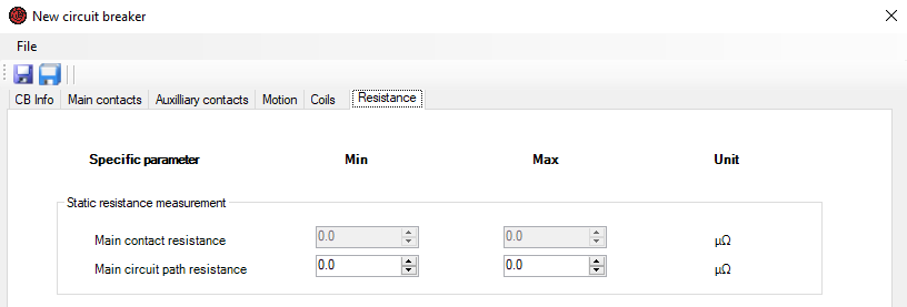
Limit values for contacts’ resistances are entered in the tab Resistance (Figure 7). Limit values for the parameter Main contact resistance can only be entered if the circuit breaker to be tested has 2 or 4 breaks per phase, and this information has been entered in the CB info tab. Certainly, the parameters of Main contact resistance and Main circuit path resistance are equal for a circuit breaker with one break per phase.
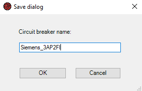
After entering all the required circuit breaker data, the next step is to save data to the database. After clicking the icon ![]() , the dialog screen will appear as shown in the Figure 8. If the circuit breaker name has not been entered, DV-Win will automatically offer the name. After saving, the circuit breaker with a selected name will appear in the Circuit breakers tab. In this way it is possible to create a customized circuit breaker’s database.
, the dialog screen will appear as shown in the Figure 8. If the circuit breaker name has not been entered, DV-Win will automatically offer the name. After saving, the circuit breaker with a selected name will appear in the Circuit breakers tab. In this way it is possible to create a customized circuit breaker’s database.
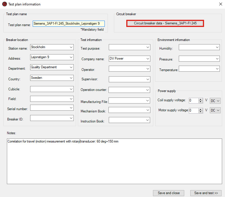
To complete a test plan, please select the newly entered circuit breaker from the Circuit Breakers tab and click the option New test plan, as shown in Figure 9. The window will appear (Figure 10) to enter information about the testing site (breaker location), test purpose, company, and weather conditions. In this window, there is the Circuit breaker data option to provide a data review about the circuit breaker to confirm the selected circuit breaker is the correct one. If the test plan is created in an office please press Save and Close, but if the test device is connected to a PC and planning to continue with testing then press Save and test. If the test plan name has not been entered, the software will automatically generate a name. After saving to the database, the test plan with the entered name will be placed in the table in the Test Plans tab.