Turns Ratio Testing – Test Results Analysis
This application note summarizes the explanation of important parameters in turns ratio testing: transformer turns ratio, turns ratio deviation, excitation current and phase angle.
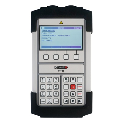
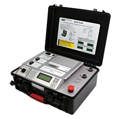
The DV Power devices intended for transformer turns ratio measurement can be used to obtain both numerical and graphical results. The graphical results are available by using the DV-Win application software suite.
The transformer parameters measured by the TRT devices are the following:
- Transformer turns ratio;
- Turns ratio deviation;
- Excitation current;
- Phase angle.
Transformer turns ratio and ratio deviation
The turns ratio of a transformer is the ratio of a number of winding turns on each side of the transformer. The turns ratio measurement is performed by applying (and measuring) an AC voltage to one side (with higher number of turns) and measuring the output voltage. This test detects shorted turns, which indicate insulation failure. Shorted turns may result from short circuits with high currents or insulation failures.
The measured turns ratio should be compared to the transformer nameplate turns ratio (the specified ratio) data.
When using the DV-Win it is sufficient to enter the number of tap positions, and the voltage values of the first and the last tap position. The software application automatically calculates the voltage values for all tap positions. It is recommended to check voltage values for all tap positions in case of a non-linear tap changer regulation. The nameplate voltage of any tap position can be changed manually.
Figure 1 Transformer nameplate voltages
Turns ratio deviation is an error indicator and shows the deviation as a percentage value of measured turns ratio and specified turns ratio. The turns ratio deviation value should not be more than 0,5% (IEC 60076-1, IEEE Std C57.12.00). The value can be considered as “pass” or “fail” based on the turns ratio deviation value. The pass/fail criteria is 0,5% by default, but it can be changed in DV-Win. The turns ratio deviation graph consists of green and white areas. If results are in green area the test is consider as “passed”.
Excitation current and phase angle
The excitation current is the corresponding current flowing in the HV winding when the LV winding is open. The results can be compared to the reference results. It is important that both tests (that are compared) are performed with nearly the same test voltage values.
The excitation current value should be compared between the phases. The excitation current of the phases which are wound on outer core legs should be approximately equal. The value of the middle phase should be lower than the values of the outside phases. If the current values are not symmetrical as described, that can indicate a core failure or asymmetrical residual flux.
The transformer should be demagnetized before the excitation current test in order to get comparable results and avoid the residual flux influence.
The phase angle and vector group detection test is important in transformer manufacturer factory to check whether the transformer windings are properly wound. Measuring the phase displacement is of interest to transformers intended for parallel operation. Also this test is important when three single phase transformers operate in a three-phase system (to check if transformer windings are properly connected). This measurement can also be used for checking phase shifting transformers, where each tap position has a different phase angle.


