Winding Resistance Measurement of Electrical Motors/Generators
In this application note, DV Power explains how to perform motor winding resistance test.
Preparation for motor winding resistance test
Prior to performing a motor winding resistance test, please make sure:
- a test object has been disconnected or separated from its circuit in accordance to the local safety regulations and is properly grounded to protective earth
- RMO-M instrument is properly grounded. To do so, connect the grounding screw on the back of the RMO-M chassis to PE using a grounding cable
- one end of the measured winding is properly grounded.
The winding contact must be clean. The terminal lugs should be cleaned with emery cloth to make sure all contaminants like paint, varnish or oxide coating is removed.
Measurement method
Motor winding resistance test uses the "Four-wire" (Kelvin) measurement method. It provides the best possible measurement results, since it ensures that the resistance of the connecting current cables is not included in the measurement.

The test current is passed through the windings using the high current cables. The voltage drop across the windings is measured using the sensing cables. Placing of the cables is very important. The current cables should always be placed outside of the sensing cables. That way, resistance of both cables and clamps is almost completely excluded from the resistance measurement (the Figure 1).
The resistance is calculated using Ohm's law and it equals voltage drop divided by the test current:
R = U / I
Motor winding resistance test
The value of the test current should be selected according to the nominal winding current. Information about nominal winding current could be found on the nameplate of the test object. The test current should not exceed 10% of the nominal winding current. Because of the heating of the cables, higher values of the test current will significantly increase the winding resistance.
- The winding resistance of three-phase AC motors is measured between their terminals (all three combinations phase by phase). Figure 2 shows the connection principle. The measurement should be repeated for all three phases, which requires connecting and disconnecting current and voltage cables.


- It is possible to measure motors’ and generators’ winding resistance in all phases at the same time. This is achieved by using three voltage sense channels and it is possible when all connection points of stator windings are accessible. Figure 4 illustrates how to connect the instrument to the machine for simultaneous resistance measurement.

- Winding resistance of a slip-ring rotor is measured directly on the slip rings (non-linear transition resistance of brushes is not included in the measured winding resistance).


Discharging motor after winding resistance test
Be aware of a possibility the energy still remains in a magnetic circuit. After the measurement has been completed RMO-M device will start the current discharging process automatically. During the current discharging ”DISCHARGING” message is will be displayed on the device’s screen.

The leads must not be removed during the discharging process. An operator should always wait for a discharging signal and a buzzer sound signal to end. That is an indication the tested motor has been properly discharged.
The current injection and energy discharging process are fully automatically regulated. The safe discharging circuit, equipped with an indicator, rapidly dissipates the stored magnetic energy after the test completion.
After all the tests have been completed, the test leads are disconnected in the following order: the test leads are removed first from the test object, then from the instrument. The mains voltage supply cable is removed first from the supply source, and then from the instrument. Finally, the ground (PE) cable should be deatached from the instrument.
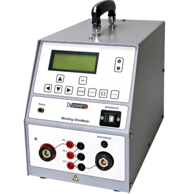
RMO50M and RMO100M
DV Power winding ohmmeters RMO50M and RMO100M are designed for measuring resistances of inductive test objects used in the electric power and other industries.
RMO50M test current is within the range of 5 mA – 50 A DC. The measuring range spans from 0,1 µΩ to 1000 Ω.
The winding ohmmeter RMO100M has the ability of testing with higher values of the test current. The test current of RMO100M is within the range of 5mA-100A DC and measuring range is between 1 µΩ to 1000 Ω.
The maximum input at the voltage sense channel is 5 V for all test current values. Having this in mind, an operator should select the test current in such a way that for the expected resistance this voltage value would not be exceeded. For example, if anticipated measuring resistance will be around 100 mΩ, the value of the test current should be below 50 A because:
U = I ∙ R
5 V = 50 A ∙ 100 mΩ
Otherwise, the error message “Change Current” will be displayed on the device. It indicates the test voltage is too high. In this case, the test current should be reduced and the test repeated.
This message is also displayed if inductivity of the test object is too high. Again, the test current should be reduced and the test repeated.