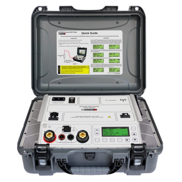
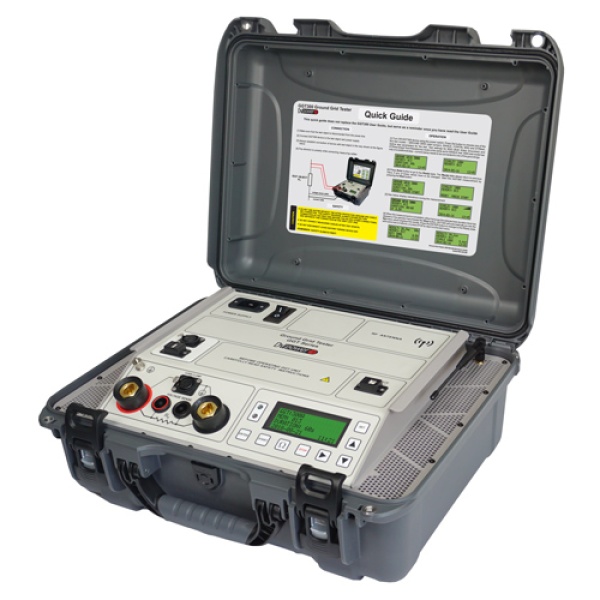
Substation Ground Grid Tester GGT200
SKU: GGT200-EU-R1
DV Power Ground Grid Tester is specially designed for integrity check of the substation grounding grids, according to IEEE80 – 2013 guidelines. It can also be used for contact resistance measurement of many different non-inductive test objects (e.g., circuit breakers) thanks to different test modes implemented.
- Test current up to 200 A
- Typical accuracy ± (0,1 % rdg + 0,1 % FS)
- Lightweight – less than 15 kg / 33 lbs
- Handheld module (GGT-M) for wireless control of the main unit
Estimated shipping time 4-5 weeks
A typical application is accurate low resistance measurement of non-inductive test objects such as:
- Earthing systems integrity/continuity test (as per IEEE 80 – 2013)
- High- and medium-voltage circuit breakers test (live and dead tank)
- Circuit breaker contact resistance measurement under BSG conditions
- High and medium voltage disconnecting switches
- High-current busbar joints
- Terminals of the conductors on HV power lines
- Continuity test of protective bonding conductors
- Oil and gas pipelines bonding
- Cable splices, welding joints, fuses, etc.
Test modes
The GGT is supplied with five different modes, GGT, SINGLE, CONTIN, DTR, and BSG. Under SINGLE mode, only the test current can be selected (up to 200 A), and under CONTIN mode, the test duration can be selected as well (up to 10 min). The DTR test mode enables testing of the dead tank circuit breakers, while BSG test mode enables contact resistance measurement of the circuit breakers when grounded from both sides. The GGT mode is implemented for grounding systems integrity/continuity tests (as per IEEE80).
Ground grid continuity and integrity test using GGT
The ground grid integrity and continuity test is described in the IEEE 80 standard, and it is one of the most efficient test methods and techniques for measuring the electrical characteristics of grounding systems. It is also known as a high-current test method, whose purpose is to check the continuity of buried ground conductors and connectors, ground rods, and bonding connections by injecting a high-test current. The integrity of earthing systems is critical to its effectiveness as the key reliability and safety mechanism of the installed equipment and electrical installations.
GGT series design
This micro-ohmmeter is a precise measuring tool that generates a true DC ripple-free current with automatically regulated test ramps. During a test the GGT ramps with increasing current before measuring and decreasing current after the measurement. This significantly decreases magnetic transients and ensures great accuracy. The pass/fail criteria is another feature that can be activated and gives the alarm if the measured resistance value is higher than the set Rmax value.
Test set
When performing a test with GGT, a single pair of current cables should be used, together with the appropriate voltage sense cables. The black marked cable (e.g., 10 m / 33 ft.) is connected to the reference grounding point in the substation (usually the transformer’s grounding). The red-marked current cable (e.g., 50 m / 165 ft.) is connected to the substation ground point under test. Since an operator needs to check several grounding points, it is very practical to use the GGT-M module for setting/changing the test parameters and remote control of the test.
| Product information | |
|---|---|
| Product name | Substation Ground Grid Tester GGT200 |
| Brand | DV Power |
| Country of origin | Sweden; |
| Measurement | |
| Test current | up to 200 A DC regulated |
| Maximum test duration | Unlimited |
| Maximum test voltage | 10 V (no load) |
| Full load voltage | 8,6 V (at 230 V AC) 7,5 V (at 115 V AC) |
| Measurement range | 0,1 µΩ – 999,9 mΩ |
| Measurement resolution | 0,1 μΩ – 1 mΩ |
| Typical accuracy | ± (0,1 % rdg + 0,1 % FS) |
| Power Supply | |
| Powered by | Mains power |
| Mains power connection according to | IEC/EN60320-1, C320 |
| Mains power input voltage | 90 V – 264 V AC |
| Mains power input frequency | 50/60 Hz |
| Power consumption | 2100 VA (at 230 V AC) 1900 VA (at 115 V AC) |
| Data Storage | |
| Storage | 500 internal memory positions |
| Computer Interface | |
| Interface | USB (standard option) Options on request RS232 and Bluetooth |
| Display | |
| Display type | 20 characters by 4 lines with backlight |
| Environmental Conditions | |
| Operating temperature | -10 ºC – +55 ºC (+14 ºF – +131 ºF) |
| Storage & transportation | -40 ºC – +70 ºC (-40 ºF – +158 ºF) |
| Humidity | up to 95 % relative humidity |
| Environmental Protection | IP 67 with closed lid |
| Applicable Standards | |
| Installation/overvoltage | CAT II IEC/EN 61010-1 |
| Pollution | degree 2 |
| Low voltage directive | Directive 2014/35/EU (CE Conform) Standard EN61010-1 (LVD Directive) |
| Electromagnetic compatibility | Directive 2014/30/EU (CE Conform) Standard EN 61326-1 |
| Accessories | |
| Test leads length | up to 60 m |
| Dimensions and Weight | |
| Dimensions (W x H x D) | 406 x 503 x 193 mm (16,0 x 19,8 x 7,6 in) |
| Weight | 14.6 kg (32,2 lbs) |
- Cable plastic case - medium size
- Ground (PE) cable
- USB cable
- Current and sense cables 2 x 35 cm 50 mm2 with alligator clamps (A4)
- Current cables 2 x 10 m 50 mm2 and heavy duty sense cables 2 x 10 m
- GGT200 device
- Plastic transport case
- Mains power cable EU 16 A
- Sense cables 2 x 1 m with alligator clamps (A2)
- USB with DV-Win software
The DV-Win software for the GGT device performs acquisition and analysis of the test results, as well as control of all the GGT functions from a PC. It also provides several advanced features as a supplement to multiple functions of GGT device. After completed measurements, the results can be saved in a various formats and test report can be generated and saved or printed. Results can also be downloaded from the device to the PC using several different search filters. The software is included in the purchase price of the device.
The main features of the software are:
- Full control of the device
- Test reports available in several formats
- Several filters for results download to PC
- Sampling time feature for CONTIN mode


